Project 4: NeRF
November 13, 2025
Overview
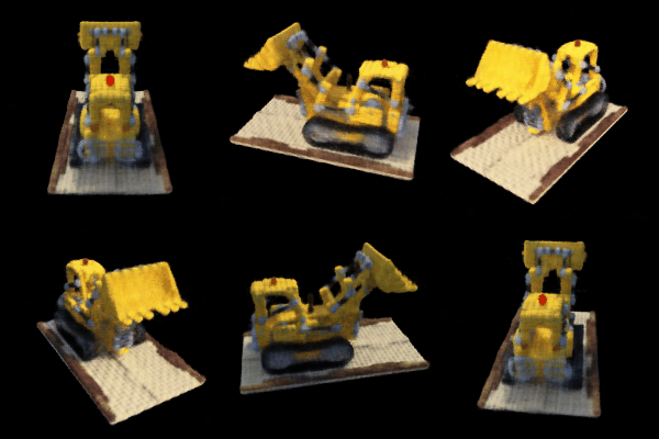
NeRF Scene Rendering
Neural Radiance Fields (NeRFs) are neural network models that can represent a 3D scene and render it from different viewpoints.
Part 0: Camera Calibration and 3D Scanning
To the first step is the recover intrisics of our camera (focal length and origin) and the extrinsics to convert from world to camera coordinates.
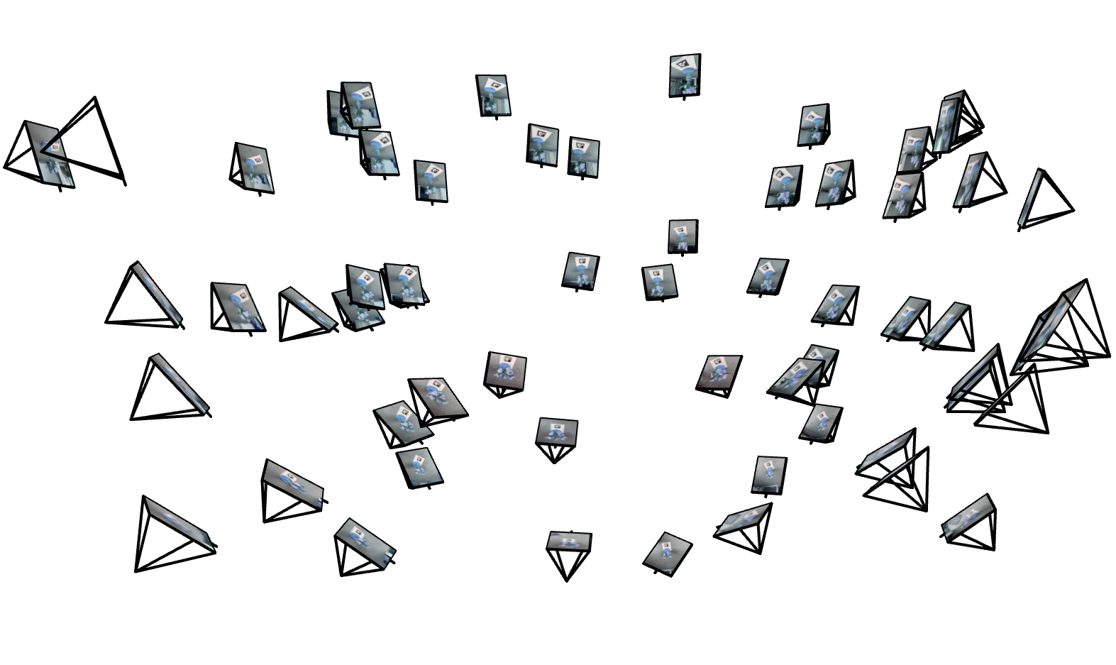
Camera Frustum Visualization 1
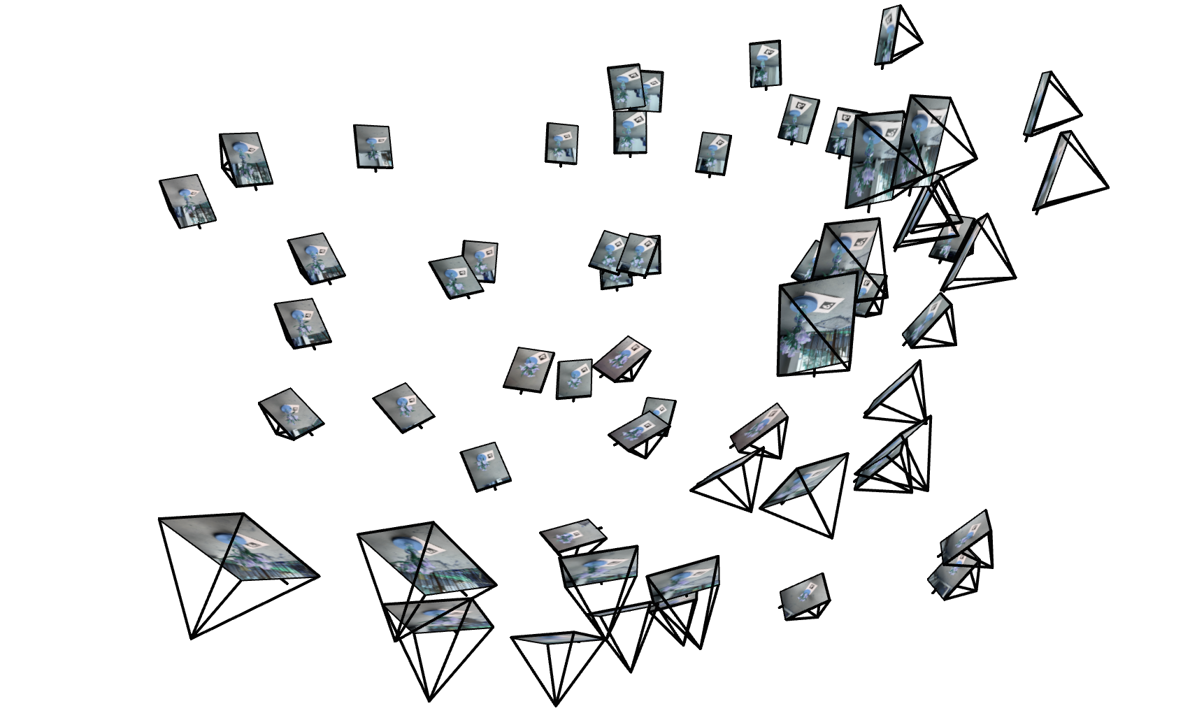
Camera Frustum Visualization 2
1: Fit a Neural Field to a 2D Image
Model architecture report
Number of Layers: 6
Width: 256
Max Positional Encoding Frequency: 10
Learning Rate: 1e-2
Training progression visualizations

Training progression visualization for test image (fox)

Training progression visualization for Byodo-In Temple, Hawaii
Final results for 2 choices of max positional encoding frequency and 2 choices of width
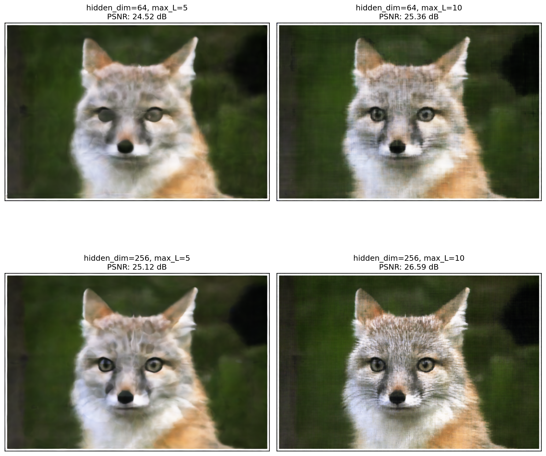
Training progression visualization for test image (fox)
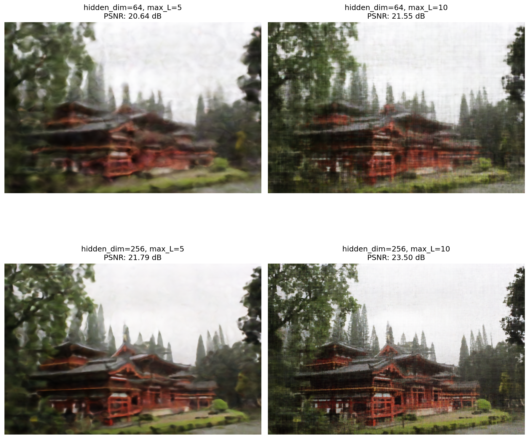
Training progression visualization for Byodo-In Temple, Hawaii
PSNR curve for training
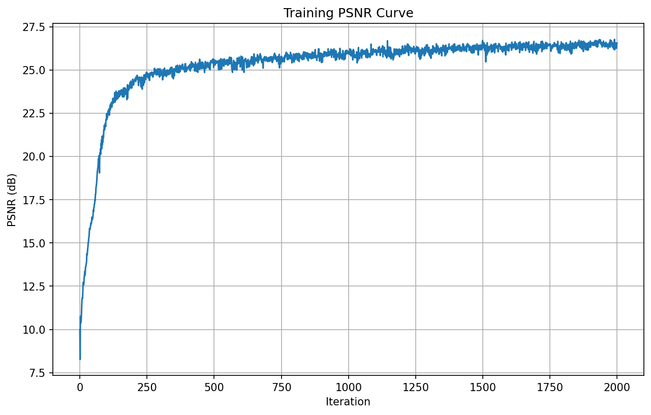
PSNR curve throughout training for fox image
2: Fit a Neural Radiance Field from Multi-view Images
Model architecture report
Number of Layers: 8
Width: 300
Max Positional Encoding Frequency for coordinates: 10
Max Positional Encoding Frequency for ray direction: 5
Learning Rate: 5e-4 with learning rate decay
Near-far : 0.5 - 2.0
Batch size: 10000 rays
Number of Samples per Ray: 64
Iterations: 20000
Brief description of Implementation:
The NeRF pipeline begins with a data preprocessing step that undistorts raw images using precomputed camera intrinsics and distortion coefficients, then computes an optimal new camera matrix that tightly crops away black borders. Each image is undistorted, cropped to the valid region of interest, converted to RGB, and ArUco markers are detected at the original resolution to recover accurate camera-to-world poses via a PnP solve. The undistorted images are then resized to a fixed target width (with focal length consistently rescaled), split into randomized train/validation sets, and packaged together with their camera poses and a scalar focal length into a single dataset file. In addition, a synthetic set of test poses is generated by computing a spiral trajectory around the object: camera centers are sampled on a circle around the mean training pose, with rotations constructed to keep the object centered, enabling smooth novel-view renderings.
During training, the dataset is wrapped in a ray-sampling loader that flattens all training images and randomly samples pixel locations across all views to form mini-batches of rays. For each batch, 3D points are sampled along each ray between configurable near and far planes with optional stratified perturbation, and the NeRF network predicts colors and densities that are integrated via volume rendering and compared against ground truth RGB with a mean squared error loss. For optimization I use Adam with an optional exponential learning rate decay schedule that is parameterized by the total number of iterations, and the training loop periodically stores rendered validation images and computes PSNR on the held-out set. The implementation also logs loss over time and generates multiple plots—training loss curves on a log scale, PSNR-vs-iteration plots.
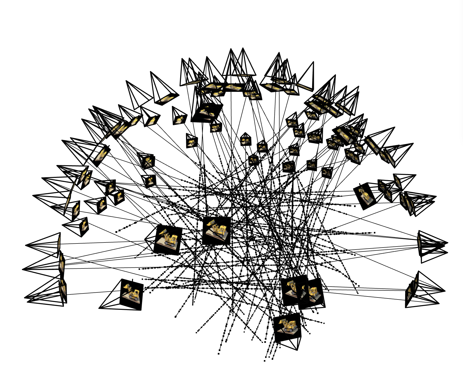
Rays and samples visualization with cameras

Training progression visualization for test image (lego)
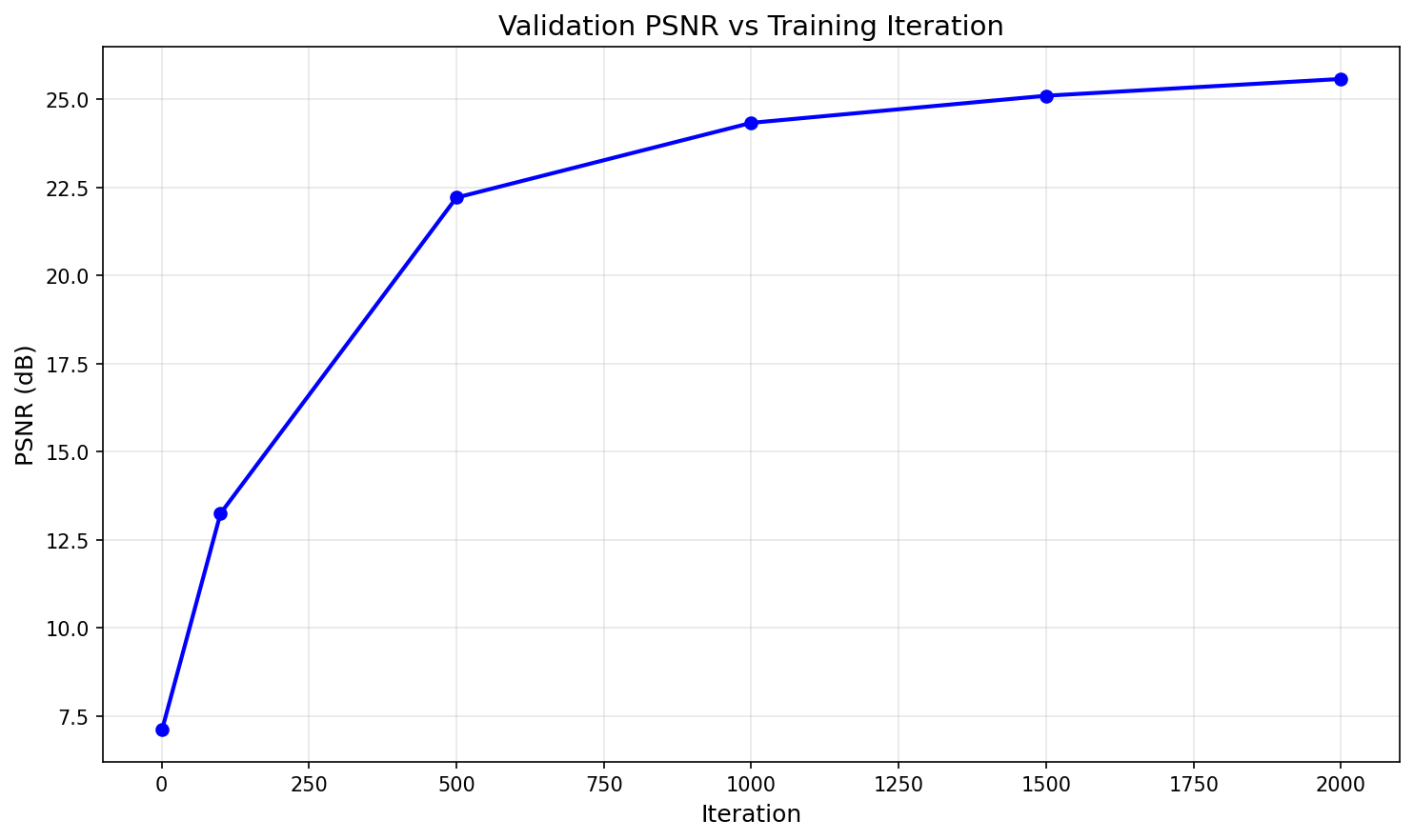
PSNR curve on validation set for lego dataset
Spherical rendering video of the Lego using provided test cameras
2.6: Training with Your Own Data
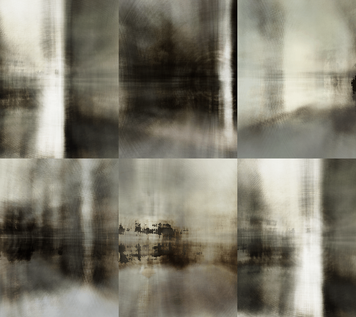
Custom NeRF Scene Rendering
Discussion of code or hyperparameter changes you made
The main thing I changed was the near-far plane distances to 0.5 and 2.0 respectively to better capture the scene depth. Additionally, I increased the network width to 300 from the 256 I used for the lego dataset. I also used learning rate decay to help with convergence over the longer training time. I kept the learning rate = 5e-4, batch_size = 10k , samples_per_ray = 64, and iterations = 2k the same as the lego dataset.
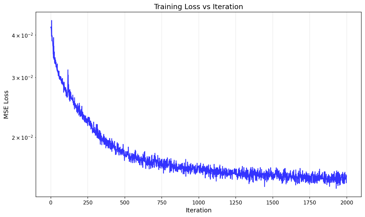
Training loss for custom image
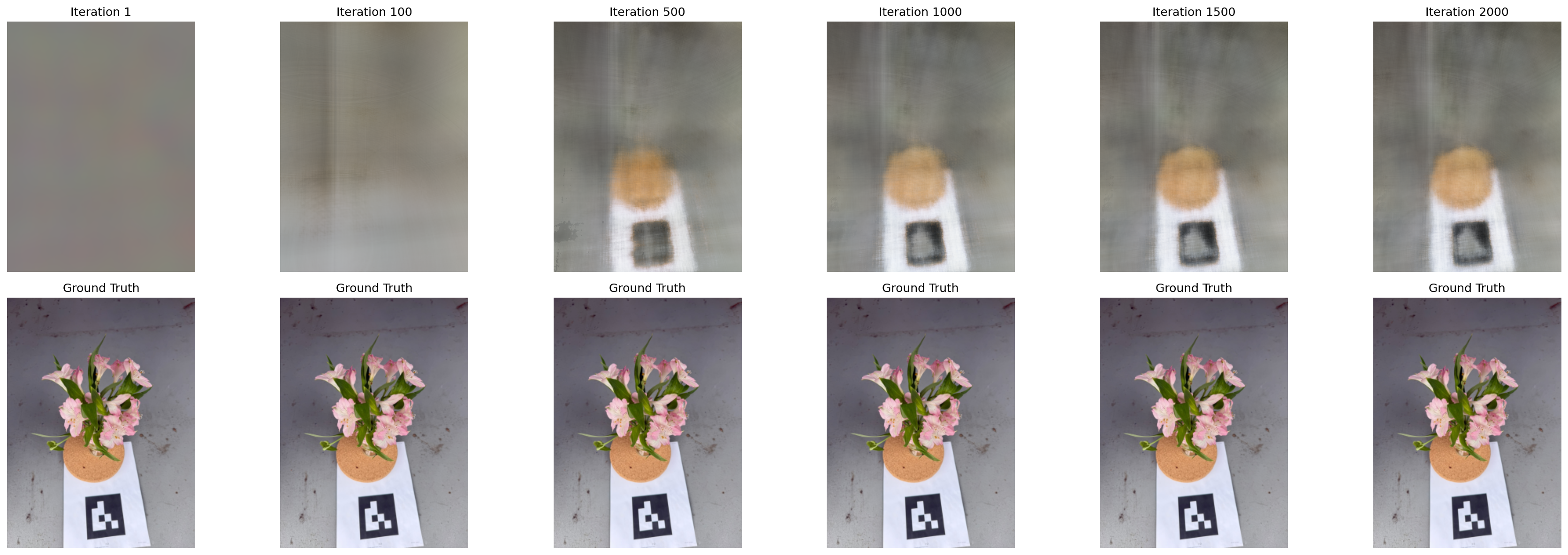
Training progression visualization for custom image